Seminar Session Recording : Tubular Control Arm Design
Looking to learn about designing tubular control arms in Fusion360? This two hour recording features Josiah Fallaise breaking down over a decade of professional reverse engineering experience into a clear, high-level workflow.
What to Expect in this Design Time:
-
-
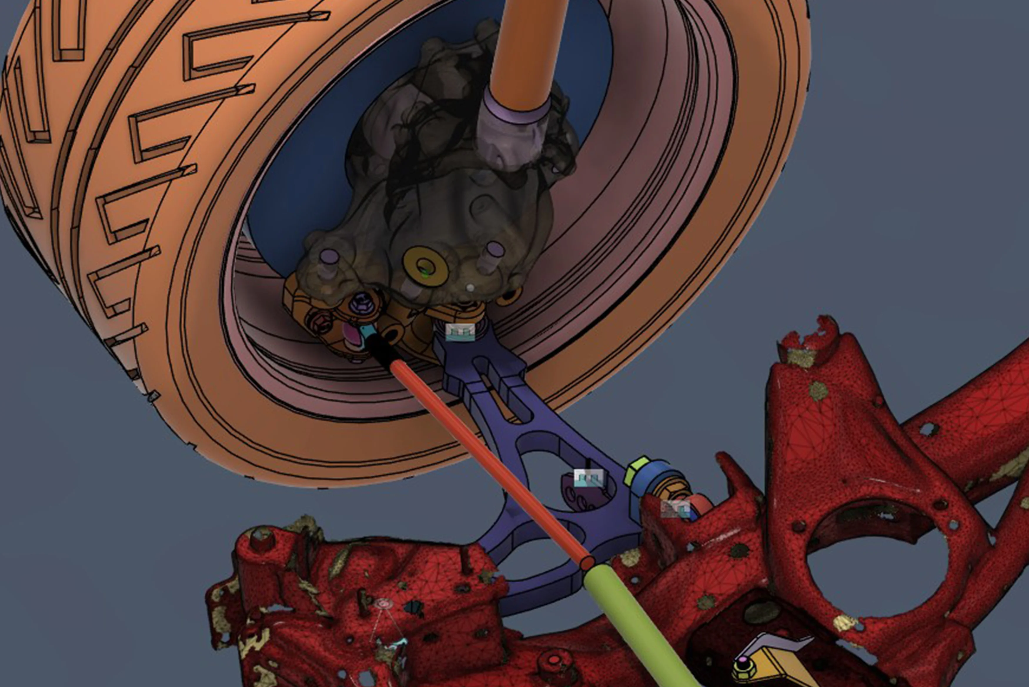
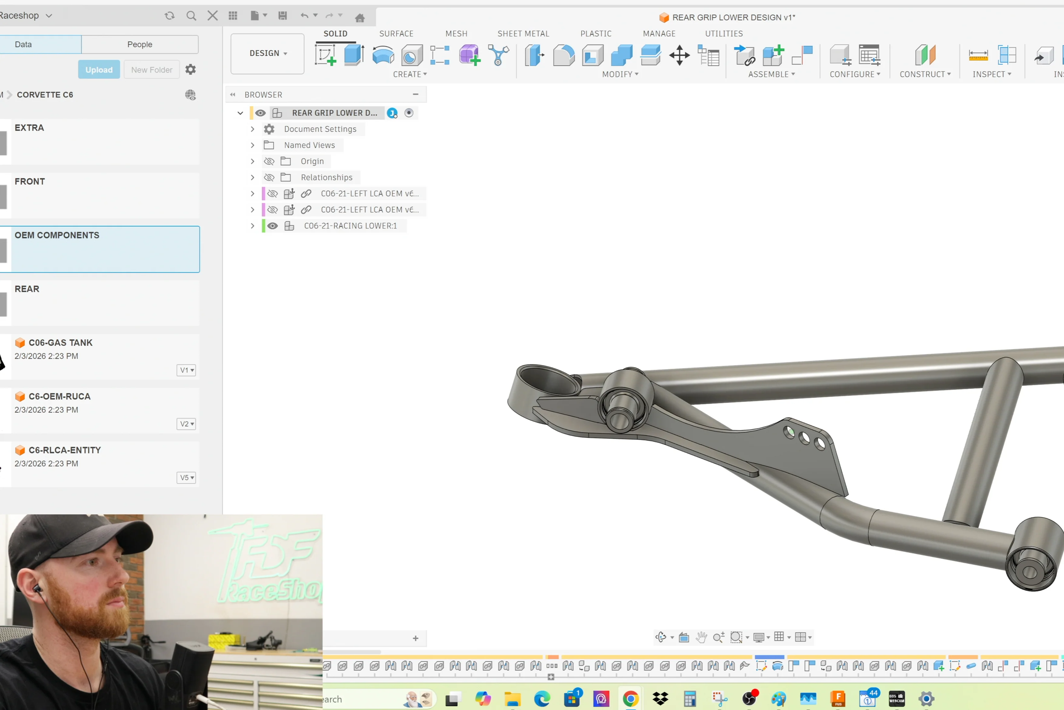
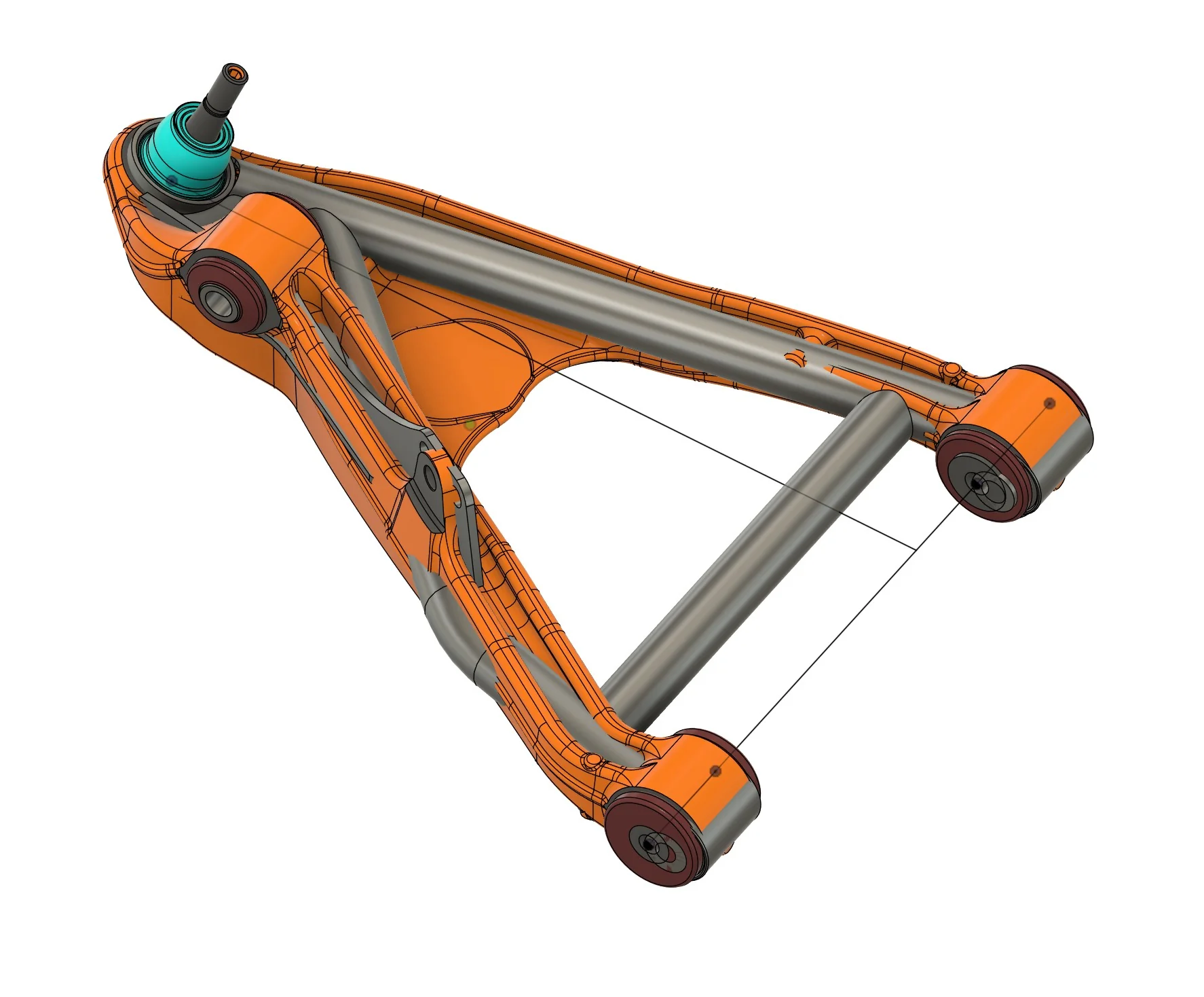
Tubular Control Arm Design - The session began with designing a tubular control arm based on an OEM C6 control arm, establishing hard points for bushings, mounts, and ball joints. The new control arm was designed to be 10 millimeters longer than stock.
- Tube Design Methodology - Each tube was designed as its own component, which makes it more controllable and results in clean exports for manufacturing. Constraints for tubes were preferred using sketches to avoid issues when tubes are notched.
- Tube Notching - The correct notching method involves using the 'split face' command on the inner and outer tube faces, selecting the other tube as the splitting tool, and then using 'press pull' to subtract the tube thickness to create an accurate cope.
- 3D Sketching and Tubing - For complex geometry, such as off-road fenders, a 3D sketch was demonstrated, emphasizing the necessity of using perpendicular controls, horizontal, and perpendicular constraints consistently.
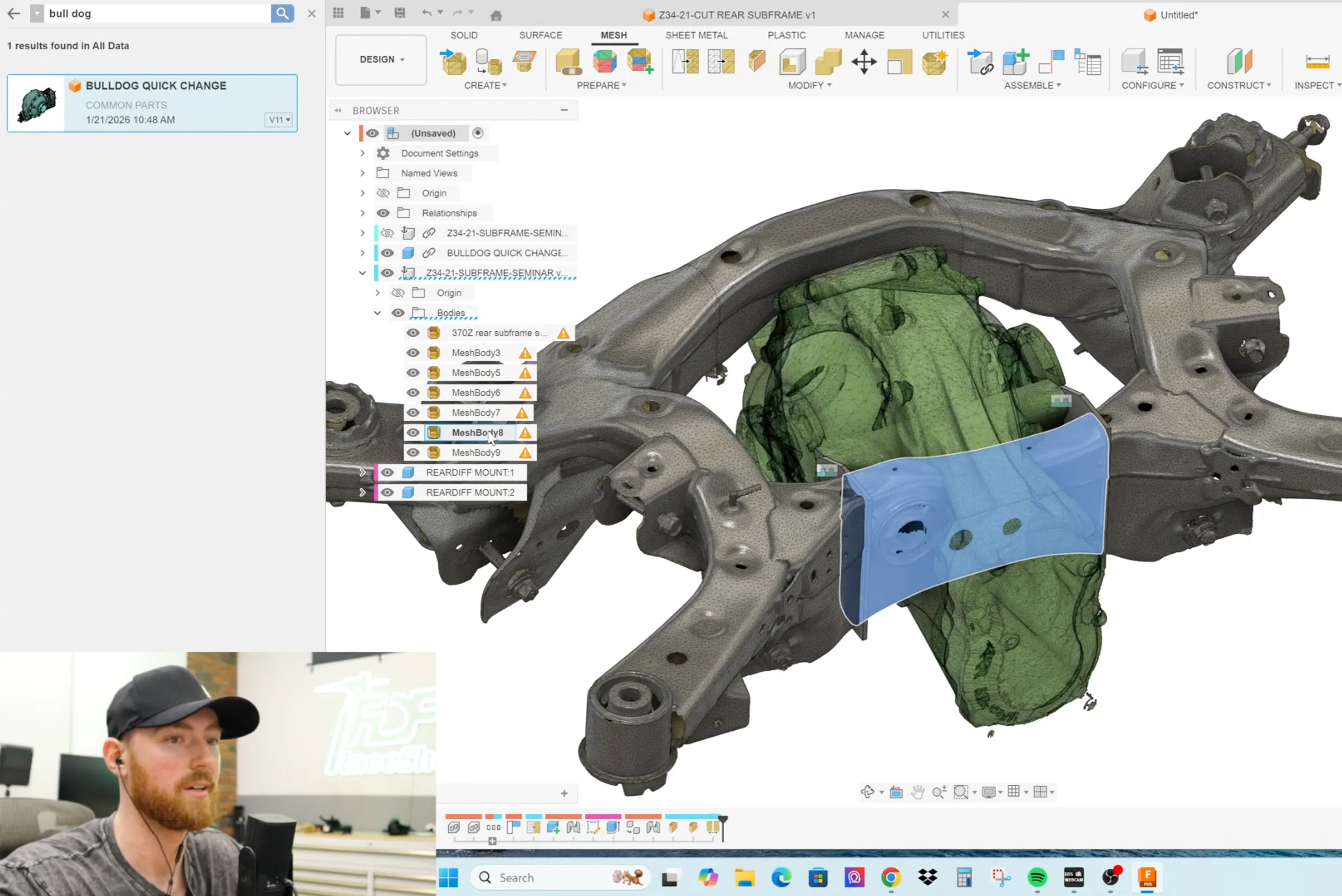
- Scan Origining and Alignment - A technique for orienting an unaligned 3D scan was shown, which involved converting the mesh to a component, using a three-point plane, creating a mesh section sketch, and using 'fit curve to mesh' to determine a center line.
- Joints vs. Constraints - Joints were explained as a faster, more controllable Fusion-specific feature, especially for complex assemblies, while constraints are a newer addition to Fusion.
- Exporting to Bentech - Step files (.STP) exported from Fusion 360 are loadable into Bentech using the "step import" feature, which converts solid 3D geometry into bend data.
-
Tubular Control Arm Design - The session began with designing a tubular control arm based on an OEM C6 control arm, establishing hard points for bushings, mounts, and ball joints. The new control arm was designed to be 10 millimeters longer than stock.
The Project
To keep things practical, Josiah walks through the entire logic of working with mesh files and advanced design techniques in Fusion 360, particularly for creating a tubular control arm.
Who This Is For
-
Fabricators fitting aftermarket parts into factory chassis.
-
Product Designers moving from scans to laser-cut parts with total confidence.
-
Engineers tired of the struggle, who want their designs to fit perfectly the first time.
Ready to fix your scan-to-design workflow?
Note: Webinar link will be shared with the email provided at the time of purchase within 48 hours purchase.
Original: $128.75
-65%$128.75
$45.06Product Information
Product Information
Shipping & Returns
Shipping & Returns
Description
Looking to learn about designing tubular control arms in Fusion360? This two hour recording features Josiah Fallaise breaking down over a decade of professional reverse engineering experience into a clear, high-level workflow.
What to Expect in this Design Time:
-
-
Tubular Control Arm Design - The session began with designing a tubular control arm based on an OEM C6 control arm, establishing hard points for bushings, mounts, and ball joints. The new control arm was designed to be 10 millimeters longer than stock.
- Tube Design Methodology - Each tube was designed as its own component, which makes it more controllable and results in clean exports for manufacturing. Constraints for tubes were preferred using sketches to avoid issues when tubes are notched.
- Tube Notching - The correct notching method involves using the 'split face' command on the inner and outer tube faces, selecting the other tube as the splitting tool, and then using 'press pull' to subtract the tube thickness to create an accurate cope.
- 3D Sketching and Tubing - For complex geometry, such as off-road fenders, a 3D sketch was demonstrated, emphasizing the necessity of using perpendicular controls, horizontal, and perpendicular constraints consistently.
- Scan Origining and Alignment - A technique for orienting an unaligned 3D scan was shown, which involved converting the mesh to a component, using a three-point plane, creating a mesh section sketch, and using 'fit curve to mesh' to determine a center line.
- Joints vs. Constraints - Joints were explained as a faster, more controllable Fusion-specific feature, especially for complex assemblies, while constraints are a newer addition to Fusion.
- Exporting to Bentech - Step files (.STP) exported from Fusion 360 are loadable into Bentech using the "step import" feature, which converts solid 3D geometry into bend data.
-
Tubular Control Arm Design - The session began with designing a tubular control arm based on an OEM C6 control arm, establishing hard points for bushings, mounts, and ball joints. The new control arm was designed to be 10 millimeters longer than stock.
The Project
To keep things practical, Josiah walks through the entire logic of working with mesh files and advanced design techniques in Fusion 360, particularly for creating a tubular control arm.
Who This Is For
-
Fabricators fitting aftermarket parts into factory chassis.
-
Product Designers moving from scans to laser-cut parts with total confidence.
-
Engineers tired of the struggle, who want their designs to fit perfectly the first time.
Ready to fix your scan-to-design workflow?
Note: Webinar link will be shared with the email provided at the time of purchase within 48 hours purchase.